Welcome!
This is a quick start guide for programming STM32 Cortex-M4 microcontollers. To get started we need to install some software.
sudo apt-get install gcc-arm-none-eabi binutils-arm-none-eabi
sudo apt-get install libnewlib-arm-none-eabi libstdc++-arm-none-eabi-newlib libnewlib-dev
sudo apt-get install gdb-arm-none-eabi openocd
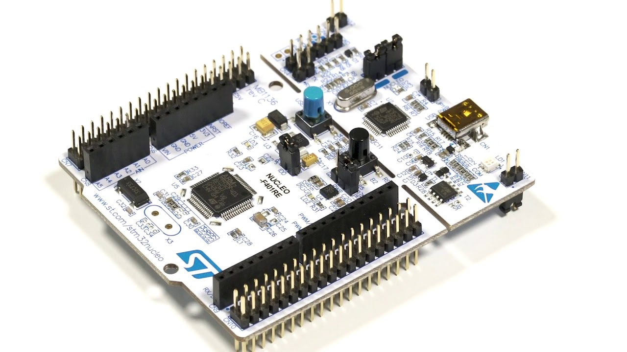
We are gonna make a simple blinky program with STM32F4 Nucleo board. I'm using Nucleo-F401RE but you can use any F4 nucleo or L4 nucleo, or any custom board that has ST's Cortex-M4 MCU, with only minor changes. This project can serve as a template project if you want to program Cortex-M4s without a HAL.
Nucleo boards have LED2 connected to GPIO pin PA5. We are gonna initialize GPIOA peripheral and use it to blink our led.
First, let's make a directory for our project
mkdir blinky
cd blinky
mkdir src
mkdir obj
mkdir src/cmsis
Now, we need to download some files. ST provides a software pack for us. (Replace this with L4 if using that and same below)
wget https://github.com/STMicroelectronics/STM32CubeF4/archive/master.zip
unzip master.zip
Let's copy Cortex-M Core related header files to our cmsis directory.
cp STM32CubeF4-master/Drivers/CMSIS/Core/Include/*.* src/cmsis/
Then STM32F4 related header files (if you have used AVRs before, these work similar to "avr/io.h").
cp STM32CubeF4-master/Drivers/CMSIS/Device/ST/STM32F4xx/Include/stm32f401xe.h src/cmsis/
cp STM32CubeF4-master/Drivers/CMSIS/Device/ST/STM32F4xx/Include/stm32f4xx.h src/cmsis/
Then system files to our src directory. These have the SystemInit function that's called before main function and also the SystemCoreClock variable.
cp STM32CubeF4-master/Drivers/CMSIS/Device/ST/STM32F4xx/Include/system_stm32f4xx.h src/
cp STM32CubeF4-master/Drivers/CMSIS/Device/ST/STM32F4xx/Source/Templates/system_stm32f4xx.c src/
And finally a startup file and linker script.
cp STM32CubeF4-master/Drivers/CMSIS/Device/ST/STM32F4xx/Source/Templates/gcc/startup_stm32f401xe.s src/
cp STM32CubeF4-master/Projects/STM32F401RE-Nucleo/Templates/SW4STM32/STM32F4xx-Nucleo/STM32F401VEHx_FLASH.ld ./
That's all the files we need and we can remove the downloaded files.
rm -rf master.zip STM32CubeF4-master/
Then we need a makefile in our project root directory. (Replace -DSTM32F401xE and -TSTM32F401VEHx_FLASH.ld if required. Also you might need to change the OpenOCD config file.)
PRG = blinky
CC = arm-none-eabi-gcc
AS = arm-none-eabi-as
O ?= 0
CFLAGS = -mcpu=cortex-m4 -mfloat-abi=hard -mfpu=fpv4-sp-d16 -mlittle-endian -mthumb -g -O$(O) -DSTM32F401xE -Isrc -Isrc/cmsis
AFLAGS = -mcpu=cortex-m4 -mfloat-abi=hard -mfpu=fpv4-sp-d16 -mlittle-endian -mthumb -g
LNKFLAGS = -mcpu=cortex-m4 -mfloat-abi=hard -mfpu=fpv4-sp-d16 -mthumb -g -TSTM32F401VEHx_FLASH.ld -Wl,--gc-sections
OCD = openocd
OCD_BRD_CFG = /usr/share/openocd/scripts/board/st_nucleo_f4.cfg
SRC := src
OBJ := obj

SOURCES := $(wildcard $(SRC)/*.c)
ASOURCES := $(wildcard $(SRC)/*.s)
OBJECTS = $(SOURCES:$(SRC)/%.c=$(OBJ)/%.o)
OBJECTS += $(ASOURCES:$(SRC)/%.s=$(OBJ)/%.o)

all: $(PRG).elf

$(PRG).elf: $(OBJECTS)
	$(CC) $(LNKFLAGS) -o $(OBJ)/$@ $^

$(OBJ)/%.o: $(SRC)/%.s
	$(AS) $(AFLAGS) -c $< -o $@

$(OBJ)/%.o: $(SRC)/%.c
	$(CC) $(CFLAGS) -c $< -o $@

program: $(PRG).elf
	$(OCD) -f $(OCD_BRD_CFG) -c "program $(OBJ)/$(PRG).elf verify reset"

clean:
	rm -f $(OBJ)/*.*
Let's create main.c in our src directory. We put all our code files there.
#include "stm32f4xx.h"

void delay(uint32_t count);

int main(void) {

	/* Enbale GPIOA clock */
	RCC->AHB1ENR |= RCC_AHB1ENR_GPIOAEN;

	/* Configure GPIOA pin 5 as output */
	GPIOA->MODER |= GPIO_MODER_MODER5_0;

	/* Configure GPIOA pin 5 in max speed */
	GPIOA->OSPEEDR |= (GPIO_OSPEEDER_OSPEEDR5_1 | GPIO_OSPEEDER_OSPEEDR5_0);

	while(1) {

		GPIOA->ODR &= ~(GPIO_ODR_OD5);
		delay(4000000);
		GPIOA->ODR |= GPIO_ODR_OD5;
		delay(1000000);
	}

	return 0;
}

void delay(uint32_t count) {
	while(count--);
}
Now our project's structure should look like this. We are gonna build into obj directory.
blinky/
+-- Makefile
+-- obj
+-- src
|   +-- cmsis
|   |   +-- cmsis_armcc.h
|   |   +-- cmsis_armclang.h
|   |   +-- cmsis_compiler.h
|   |   +-- cmsis_gcc.h
|   |   +-- cmsis_iccarm.h
|   |   +-- cmsis_version.h
|   |   +-- core_armv8mbl.h
|   |   +-- core_armv8mml.h
|   |   +-- core_cm0.h
|   |   +-- core_cm0plus.h
|   |   +-- core_cm1.h
|   |   +-- core_cm23.h
|   |   +-- core_cm33.h
|   |   +-- core_cm3.h
|   |   +-- core_cm4.h
|   |   +-- core_cm7.h
|   |   +-- core_sc000.h
|   |   +-- core_sc300.h
|   |   +-- mpu_armv7.h
|   |   +-- mpu_armv8.h
|   |   +-- stm32f401xe.h
|   |   +-- stm32f4xx.h
|   |   +-- tz_context.h
|   +-- main.c
|   +-- startup_stm32f401xe.s
|   +-- system_stm32f4xx.c
|   +-- system_stm32f4xx.h
+-- STM32F401VEHx_FLASH.ld
Let's dig in to the code and take a look at the Reference manual of our MCU.
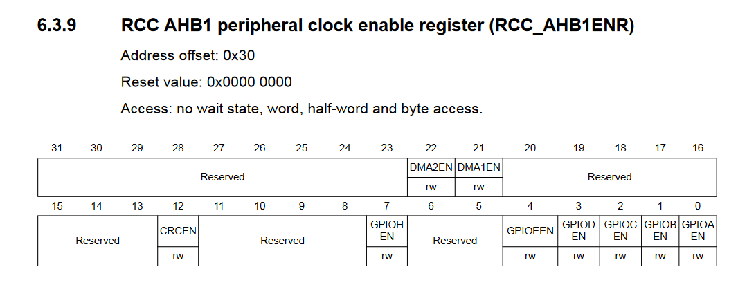
Let's find the Reset and clock control (RCC) that controls the clocks for GPIO and if we look at AHB1 peripheral clock enable register (RCC_AHB1ENR) we can see the bits that control different IO port clocks.
We set bit 0 with RCC->AHB1ENR |= RCC_AHB1ENR_GPIOAEN; to enable clock for port A.
Where do these register names and definitions come from? They come form "stm32f401xe.h" that's included by "stm32f4xx.h" based on -DSTM32F401xE in the makefile. Take a look at it, it has all the definitions you need.
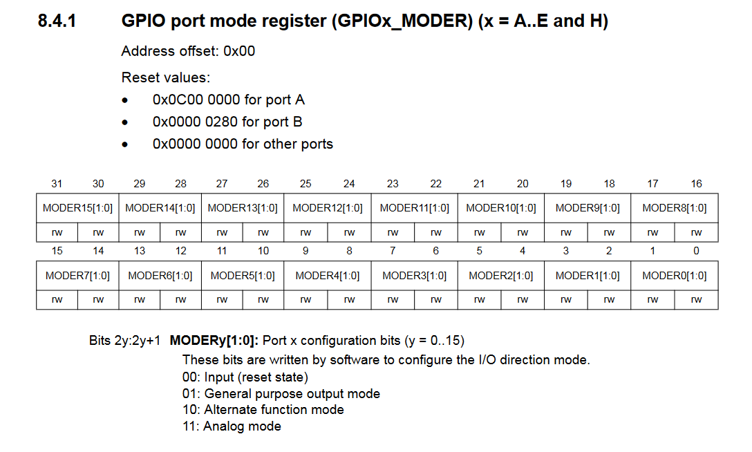
Now our GPIOA is ready to use. First let's set pin PA5 mode to output. Let's look at GPIO port mode register (GPIOx_MODER).
We have 16 pins and every pin has 2 config bits.
We set bit 10 with GPIOA->MODER |= GPIO_MODER_MODER5_0; to config PA5 to General purpose output mode.
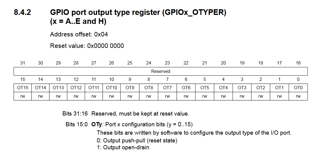
Let's look at GPIO port output type register (GPIOx_OTYPER). We want push-pull output and its the reset state, so we dont have to do anything for this register.
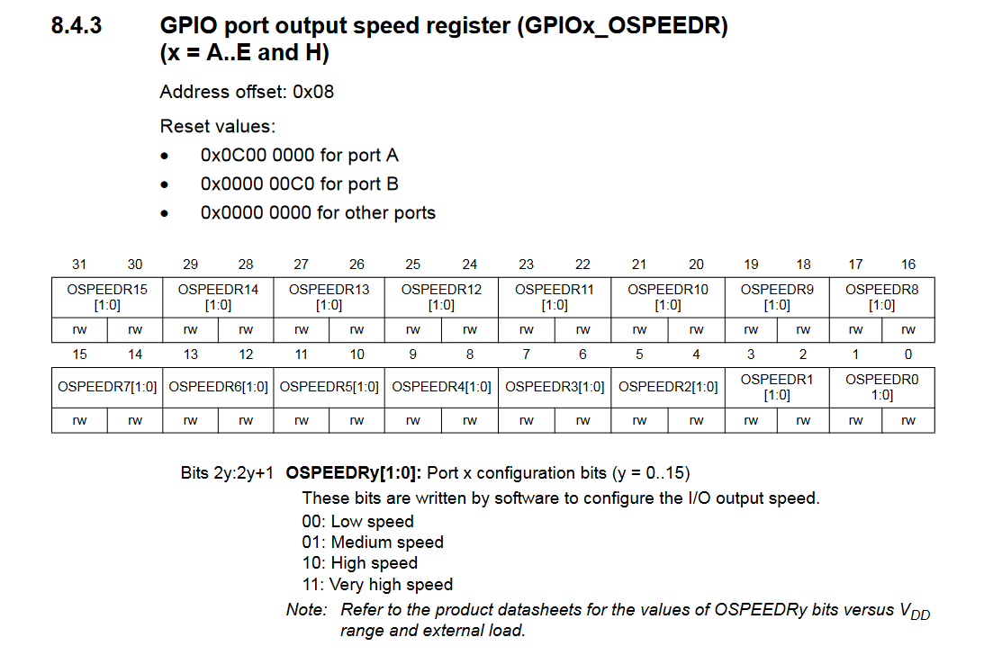
Next we look at GPIO port output speed register (GPIOx_OSPEEDR) and set bits 10 and 11 with GPIOA->OSPEEDR |= (GPIO_OSPEEDER_OSPEEDR5_1 | GPIO_OSPEEDER_OSPEEDR5_0); to select very high speed for PA5.
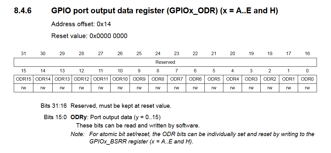
And here is the main loop of our program, we clear bit 5 in GPIO port output data register (GPIOx_ODR), wait for a while, set bit 5 in the same register and then wait again.
	while(1) {

		GPIOA->ODR &= ~(GPIO_ODR_OD5);
		delay(4000000);
		GPIOA->ODR |= GPIO_ODR_OD5;
		delay(1000000);
	}

	return 0;
And here's our simple delay function. We will make a better one later.
void delay(uint32_t count) {
	while(count--);
}
Now everything is ready and we can compile and program the device.
make program
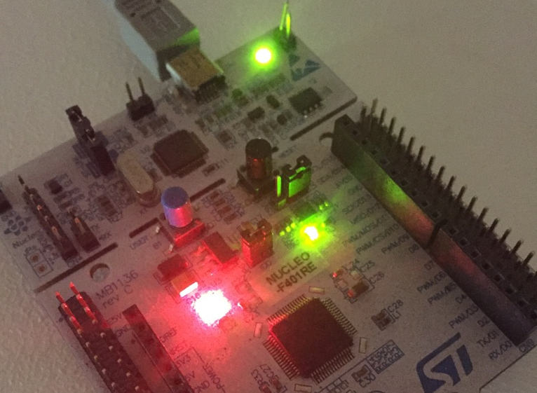
And there we go, you should have a (green) led blinking now. Next we are gonna setup the clock system and make a millisecond delay.
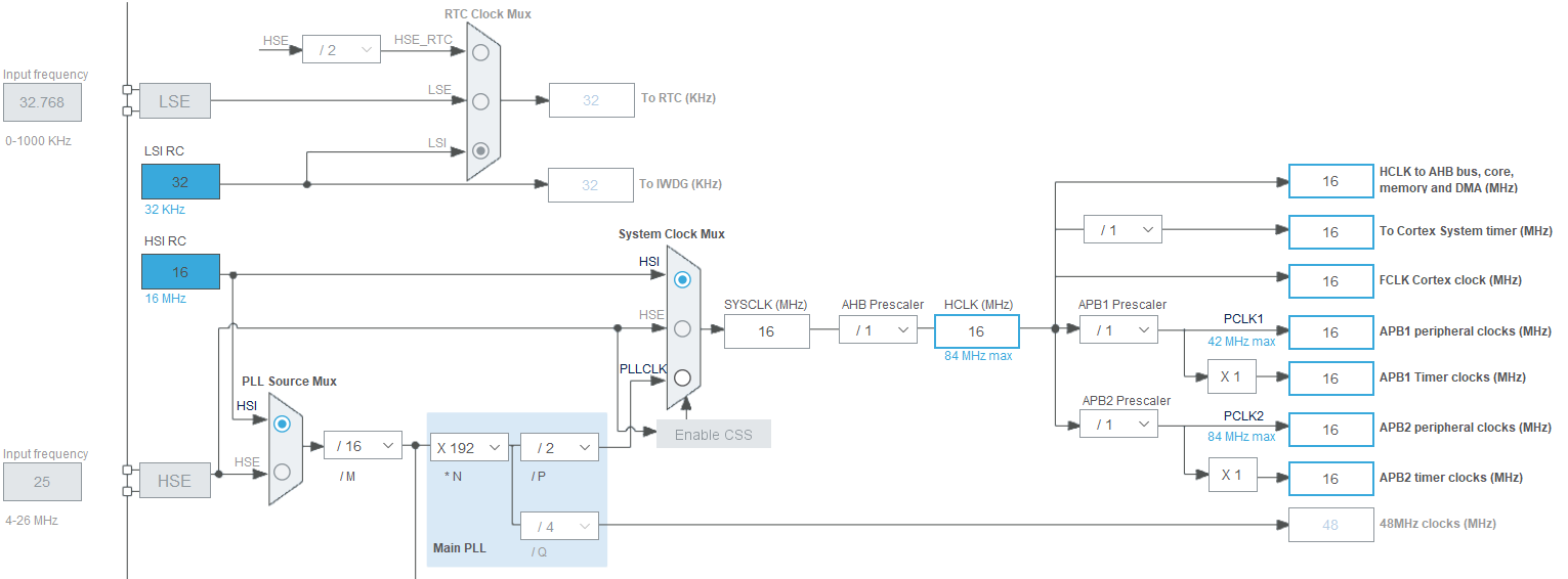
Now, let's look at the picture below, it shows the default clock configuration. After a system reset, the 16 MHz HSI oscillator (1% accuracy) is selected as the system clock and it also provides clocks to AHB, APB1 and APB2. Prescalers are used to configure the AHB frequency, the high-speed APB(APB2) frequency and the low-speed APB(APB1) frequency. So in the default state, everything runs at 16 MHz.
Let's use the System Timer to generate an interrupt every millisecond. CMSIS provides a function for this, SysTick_Config(), that is used to initialize the SysTick event. This function can be found in the file core_cm4.h in cmsis directory.
The function takes the number of ticks between two interrupts as a parameter and initializes the system timer and its interrupt and starts it. Your must implement an ISR called SysTick_Handler() which is called every time the SysTick event fires.
We get one millisecond period between interrupts by dividing SYSCLK(16MHz) by 1KHz. We can use the SystemCoreClock variable from system_stm32f4xx.c, its default value is 16000000.
SysTick_Config(SystemCoreClock / 1000U);
Now let's create a variable that counts our one millisecond ticks and also the ISR where we increment this variable. We also need the delay function. So now our main.c should look like this.
#include "stm32f4xx.h"
#include "system_stm32f4xx.h"

volatile uint32_t tick_millis;

void delay_ms(uint32_t millis);

int main(void) {

	tick_millis = 0;

	/* SysTick tick freq 1KHz */
	SysTick_Config(SystemCoreClock / 1000U);

	/* Enbale GPIOA clock */
	RCC->AHB1ENR |= RCC_AHB1ENR_GPIOAEN;

	/* Configure GPIOA pin 5 as output */
	GPIOA->MODER |= GPIO_MODER_MODER5_0;

	/* Configure GPIOA pin 5 in max speed */
	GPIOA->OSPEEDR |= (GPIO_OSPEEDER_OSPEEDR5_1 | GPIO_OSPEEDER_OSPEEDR5_0);

	while(1) {

		GPIOA->ODR &= ~(GPIO_ODR_OD5);
		delay_ms(1000);
		GPIOA->ODR |= GPIO_ODR_OD5;
		delay_ms(1000);
	}
	return 0;
}

void delay_ms(uint32_t millis) {
	uint32_t start = tick_millis;
	while((tick_millis - start) < millis);
}

void SysTick_Handler(void) {
	tick_millis++;
}
We can compile and program the device.
make program
You should have a led blinking with 1000 millisecond delay.
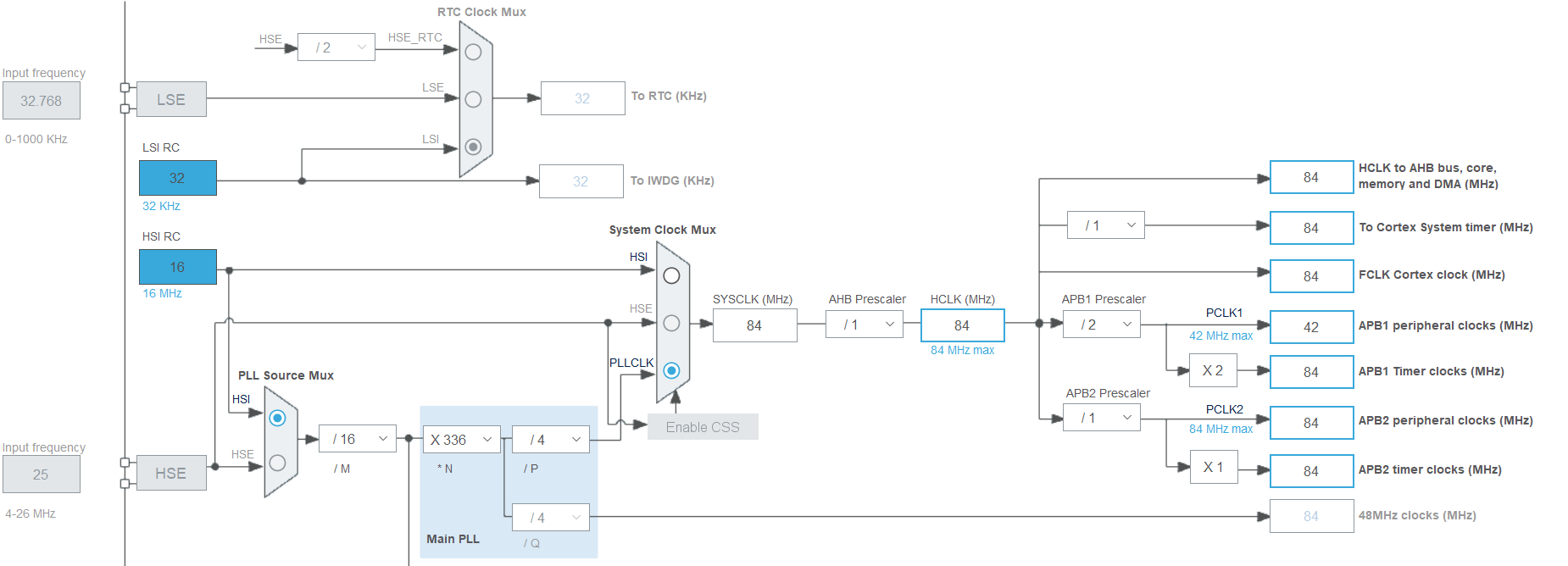
Next let's utilize the main PLL so we can have higher system clock frequency. Our goal is shown in the picture below, we are gonna set the system clock to 84MHz. We need to config the PLL and set it as system clock source. We also need to set the prescaler for APB1 since its max frequency is 42MHz.
Let's create a function for this.
void clock_init(void) {

	/* Zero out PLL M */
	RCC->PLLCFGR &= ~(RCC_PLLCFGR_PLLM);
	/* PLL M = 16 */
	RCC->PLLCFGR |= RCC_PLLCFGR_PLLM_4;

	/* Zero out PLL N */
	RCC->PLLCFGR &= ~(RCC_PLLCFGR_PLLN);
	/* PLL N = 336 */
	RCC->PLLCFGR |= (RCC_PLLCFGR_PLLN_8 | RCC_PLLCFGR_PLLN_6 | RCC_PLLCFGR_PLLN_4);

	/* Zero out PLL P */
	RCC->PLLCFGR &= ~(RCC_PLLCFGR_PLLP);
	/* PLL P = 4 */
	RCC->PLLCFGR |= RCC_PLLCFGR_PLLP_0;

	/* Zero out APB1 Prescaler */
	RCC->CFGR &= ~(RCC_CFGR_PPRE1);
	/* APB1 Prescaler = 2 */
	RCC->CFGR |= RCC_CFGR_PPRE1_DIV2;

	/* Activate PLL */
	RCC->CR |= RCC_CR_PLLON;

	/* Wait until PLL is locked */
	while(!(RCC->CR & RCC_CR_PLLRDY));

	/* Set Flash Latency */
	FLASH->ACR |= FLASH_ACR_LATENCY_2WS;

	/* Set PLL as System Clock */
	RCC->CFGR |= RCC_CFGR_SW_PLL;

	SystemCoreClockUpdate();
}
Let's look at the Reference manual again. Take a look at the PLL configuration register (RCC_PLLCFGR). We have config bits for PLLM(6 bits), PLLN(9 bits) and PLLP(2 bits) values. We need to set them to values like in the picture above. PLLM = 16, PLLN = 336, PLLP = 4
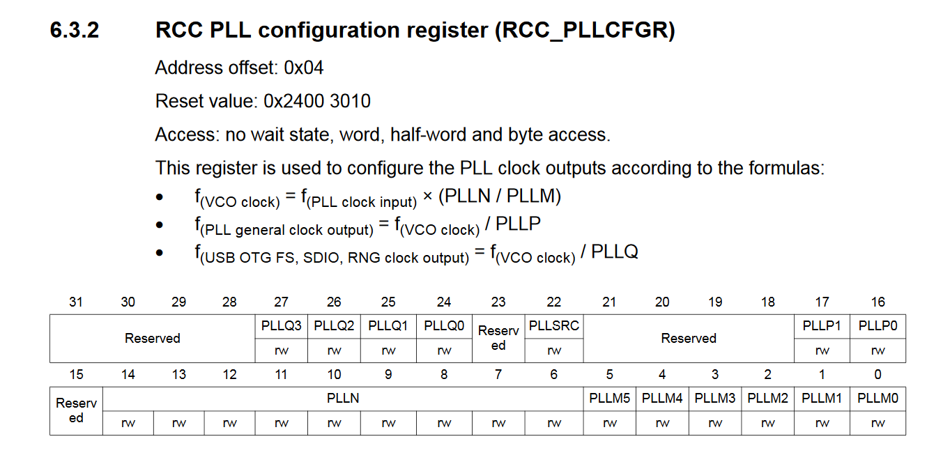
First we zero out the PLLM bits with RCC->PLLCFGR &= ~(RCC_PLLCFGR_PLLM); because they have a non-zero default value after reset.
Then we set bit 4 with RCC->PLLCFGR |= RCC_PLLCFGR_PLLM_4; to get binary value 010000 which is 16 in decimal.
Again we zero out the PLLN bits with RCC->PLLCFGR &= ~(RCC_PLLCFGR_PLLN);
Then we set bits 10, 12 and 14 with RCC->PLLCFGR |= (RCC_PLLCFGR_PLLN_8 | RCC_PLLCFGR_PLLN_6 | RCC_PLLCFGR_PLLN_4); to get binary value 101010000 which is 336 in decimal.
Again we zero out the PLLP bits with RCC->PLLCFGR &= ~(RCC_PLLCFGR_PLLP);
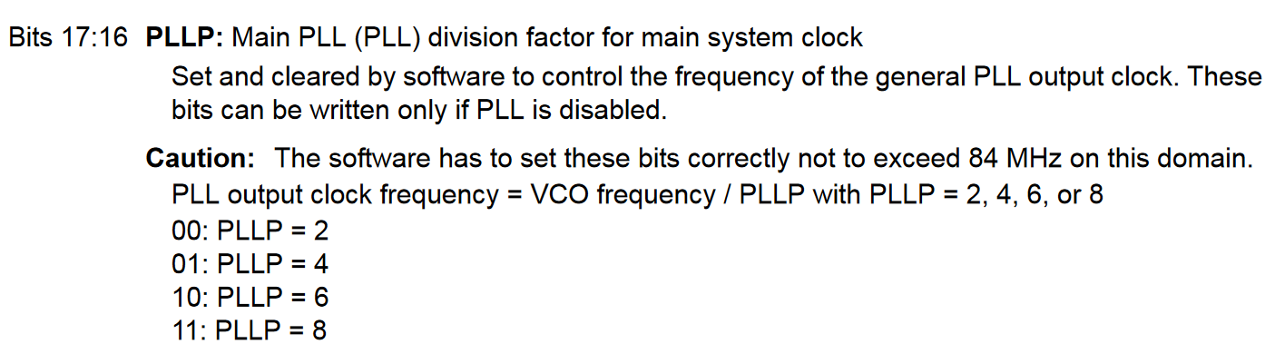
Then we set bit 16 with RCC->PLLCFGR |= RCC_PLLCFGR_PLLP_0; to get binary value 01 which translates to 4, according to the picture below.
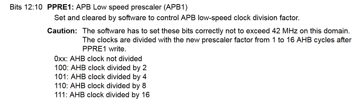
Now, let's look at the RCC clock config register (RCC_CFGR). We need to set APB1 prescaler value to 2. PPRE1(3 bits) defines the prescaler value.
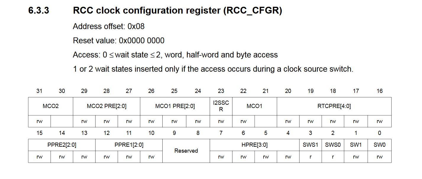
We zero out the PPRE1 bits with RCC->CFGR &= ~(RCC_CFGR_PPRE1);
Then we set bit 12 with RCC->CFGR |= RCC_CFGR_PPRE1_DIV2; to get binary value 100 which translates to 2, according to the picture below.
Next we need to activate the PLL, take a look at the RCC clock control register (RCC_CR).
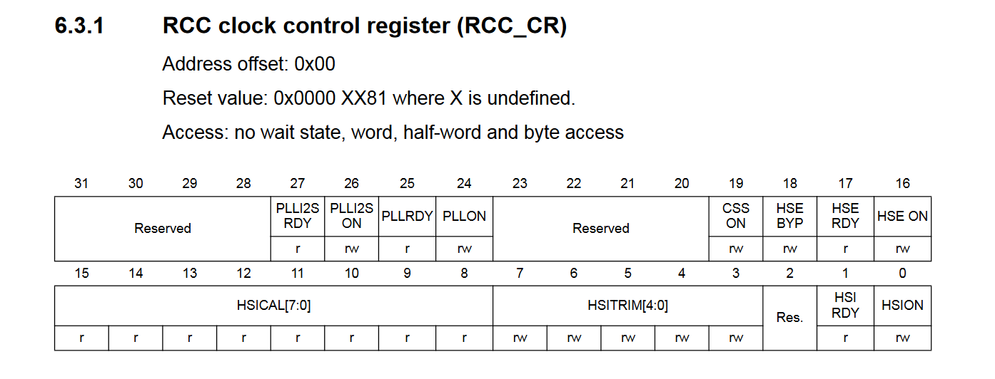
First we set bit 24 with RCC->CR |= RCC_CR_PLLON; to activate the PLL.
Then we keep reading bit 25 and wait until the PLL is locked with while(!(RCC->CR & RCC_CR_PLLRDY));
Now, we need to do one more thing before switching the PLL to system clock. We need to add wait states to Flash memory reads because we now operate at much higher CPU frequency. Picture below has a table about this.
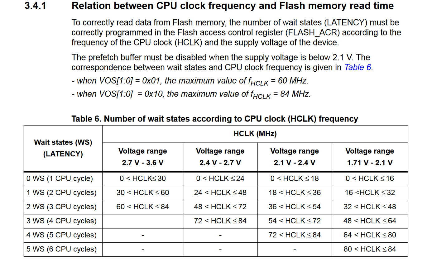
Our supply voltage is 3.3V and our CPU freq is 84MHz so we need 2 wait states. Let's look at the Flash access control register (FLASH_ACR), bits 0, 1, 2 and 3 are used to set the latency value.
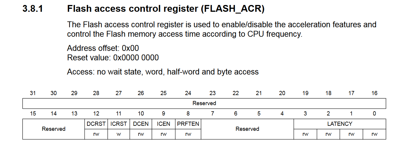
We set bit 1 with FLASH->ACR |= FLASH_ACR_LATENCY_2WS; to get binary value 0010 which is 2 in decimal.
We already looked at RCC clock config register (RCC_CFGR) above, first 2 bits define the clock source.
We set the PLL as system clock by setting bit 1 with RCC->CFGR |= RCC_CFGR_SW_PLL;
Finally we need to update the SystemCoreClock variable by calling SystemCoreClockUpdate();
Our final version of main.c should look like this.
#include "stm32f4xx.h"
#include "system_stm32f4xx.h"

volatile uint32_t tick_millis;

void clock_init(void);
void delay_ms(uint32_t millis);

int main(void) {

	clock_init();

	tick_millis = 0;

	/* SysTick tick freq 1KHz */
	SysTick_Config(SystemCoreClock / 1000U);

	/* Enbale GPIOA clock */
	RCC->AHB1ENR |= RCC_AHB1ENR_GPIOAEN;

	/* Configure GPIOA pin 5 as output */
	GPIOA->MODER |= GPIO_MODER_MODER5_0;

	/* Configure GPIOA pin 5 in max speed */
	GPIOA->OSPEEDR |= (GPIO_OSPEEDER_OSPEEDR5_1 | GPIO_OSPEEDER_OSPEEDR5_0);

	while(1) {

		GPIOA->ODR &= ~(GPIO_ODR_OD5);
		delay_ms(1000);
		GPIOA->ODR |= GPIO_ODR_OD5;
		delay_ms(1000);
	}
	return 0;
}

void clock_init(void) {

	/* Zero out PLL M */
	RCC->PLLCFGR &= ~(RCC_PLLCFGR_PLLM);
	/* PLL M = 16 */
	RCC->PLLCFGR |= RCC_PLLCFGR_PLLM_4;

	/* Zero out PLL N */
	RCC->PLLCFGR &= ~(RCC_PLLCFGR_PLLN);
	/* PLL N = 336 */
	RCC->PLLCFGR |= (RCC_PLLCFGR_PLLN_8 | RCC_PLLCFGR_PLLN_6 | RCC_PLLCFGR_PLLN_4);

	/* Zero out PLL P */
	RCC->PLLCFGR &= ~(RCC_PLLCFGR_PLLP);
	/* PLL P = 4 */
	RCC->PLLCFGR |= RCC_PLLCFGR_PLLP_0;

	/* Zero out APB1 Prescaler */
	RCC->CFGR &= ~(RCC_CFGR_PPRE1);
	/* APB1 Prescaler = 2 */
	RCC->CFGR |= RCC_CFGR_PPRE1_DIV2;

	/* Activate PLL */
	RCC->CR |= RCC_CR_PLLON;

	/* Wait until PLL is locked */
	while(!(RCC->CR & RCC_CR_PLLRDY));

	/* Set Flash Latency */
	FLASH->ACR |= FLASH_ACR_LATENCY_2WS;

	/* Set PLL as System Clock */
	RCC->CFGR |= RCC_CFGR_SW_PLL;

	SystemCoreClockUpdate();
}

void delay_ms(uint32_t millis) {
	uint32_t start = tick_millis;
	while((tick_millis - start) < millis);
}

void SysTick_Handler(void) {
	tick_millis++;
}
We can compile and program the device.
make program
Where to go next ?
Well, you can read more about the RCC and also NVIC which is the interrupt controller. You should also check out the Adaptive real-time memory accelerator (ART Accelerator) which can be used to remedy the wait states we inserted. You can try to setup UART for serial communication or try to read external analog voltage with ADC. Both of these peripherals are fairly easy to setup. You should also improve the delay function so it takes into account the possible overflow situation.
nohit 2020/2021